Appendix 5 - Markers synchronization
Is possible to take advantage of the OpenBCI construction, this board includes a set of analog and digital inputs that can be used to synchronize markers. Other systems will need a piece of additional laboratory equipment like LabStreamer that can register time with microseconds precision. In order to use OpenBCI, we will only need an LDR module connected to the pin D11 (or A5) and start the automatic latency correction system. This method is similar to the one implemented by .
[3]:
reader = HDF5Reader('data/record-markers_offset.h5')
aux = reader.aux
aux_timestamp = reader.aux_timestamp
markers = reader.markers
print(reader)
==========
data/record-markers_offset.h5
2021-10-28 22:10:49.579271
==========
MARKERS: ['Right', '1', 'Retention', 'No-changed', 'No-response', 'Left', 'Identical', '2', 'Changed', 'Different', '4']
SAMPLE_RATE: 1000
STREAMING_SAMPLE_RATE: 100
DATETIME: 1635477049.579271
MONTAGE: standard_1020
CHANNELS: {1: 'Fp1', 2: 'Fp2', 3: 'F7', 4: 'F3', 5: 'Fz', 6: 'F4', 7: 'F8', 8: 'T7', 9: 'T8', 10: 'P7', 11: 'P3', 12: 'Pz', 13: 'P4', 14: 'P8', 15: 'O1', 16: 'O2'}
CHANNELS_BY_BOARD: [16]
SHAPE: [16, 1527998]
DURATION: 1528.0 seconds (25.5 minutes)
==========
Rise-up detectors
The method get_rises will return the timestamps locations of the rise-ups in the signal.
[4]:
lower_val = 260
upper_val = 750
rises = reader.get_rises(aux[0], aux_timestamp[0], lower=lower_val, upper=upper_val)
[5]:
plt.figure(figsize=(20, 5), dpi=90)
plt.grid(True)
plt.plot(aux_timestamp[0], aux[0], color='C0', label='Aux')
plt.hlines(lower_val, 0, aux_timestamp[0][-1], color='C2', linestyle='--', label='Lower limit')
plt.hlines(upper_val, 0, aux_timestamp[0][-1], color='C3', linestyle='--', label='Upper limit')
plt.vlines(rises, lower_val, upper_val, color='C1', linestyle='--')
plt.ylim(lower_val-50, upper_val+50)
plt.xlim(20000, 40000)
plt.legend()

plt.xlabel('Time [ms]')
plt.ylabel('Amplitude')
[5]:
Text(0, 0.5, 'Amplitude')
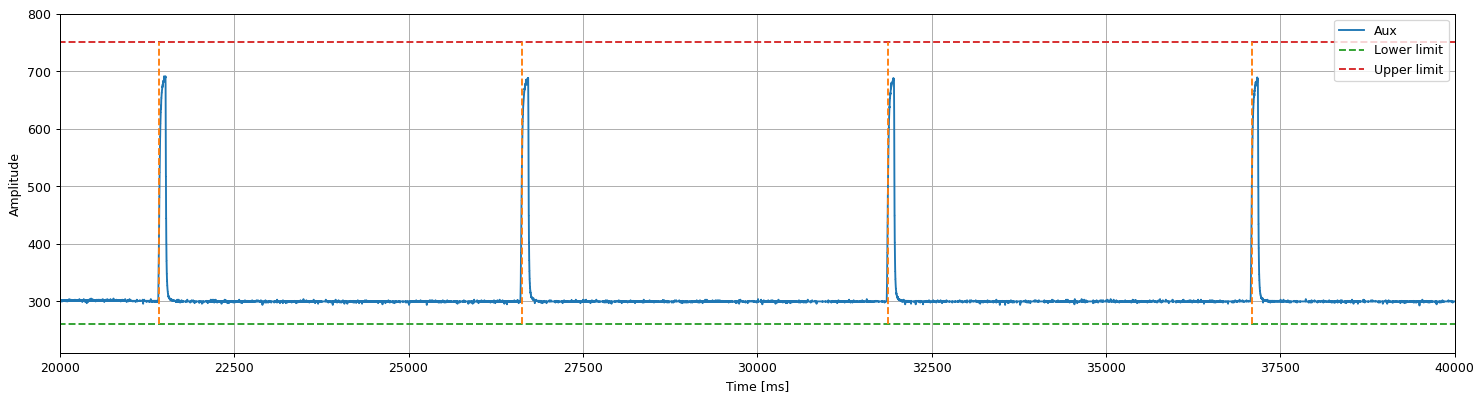
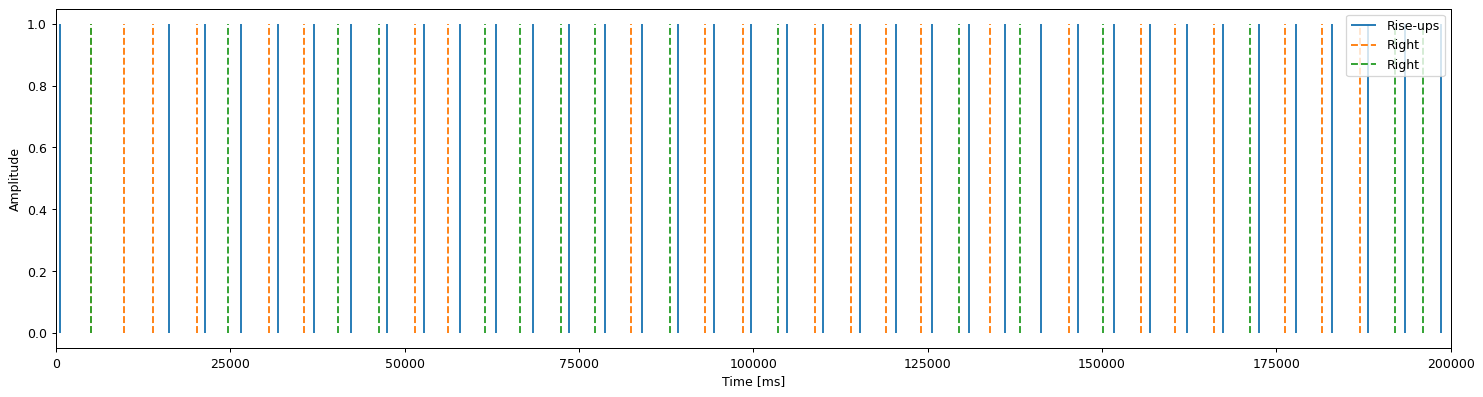
This rise-ups will show the markers offsets:
[6]:
plt.figure(figsize=(20, 5), dpi=90)

plt.vlines(rises, 0, 1, color='C0', label='Rise-ups')
plt.vlines(markers['Right'], 0, 1, color='C1', linestyle='--', label='Right')
plt.vlines(markers['Left'], 0, 1, color='C2', linestyle='--', label='Right')

plt.legend()
plt.xlim(0, 2e5)

plt.xlabel('Time [ms]')
plt.ylabel('Amplitude')
[6]:
Text(0, 0.5, 'Amplitude')
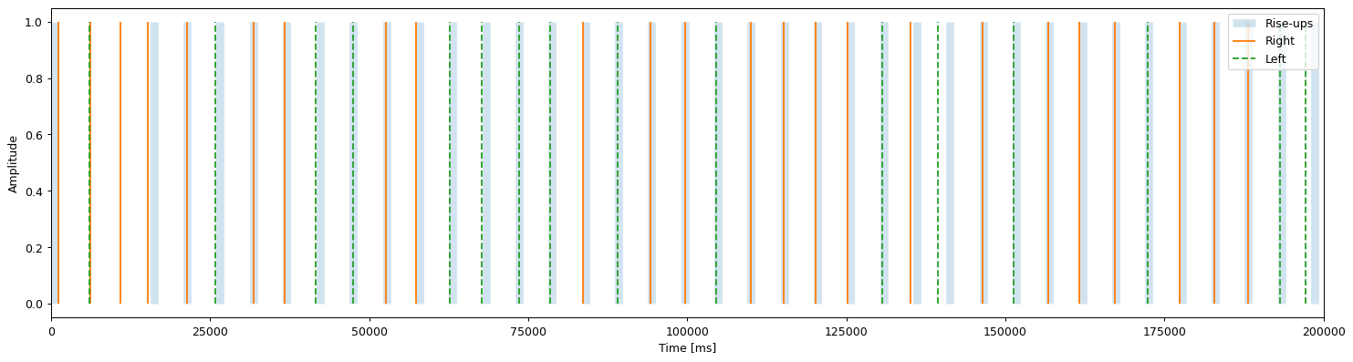
Markers synchronization
With the rises is possible to relocate the markers by calculating the offsets with the method fix_markers:
[7]:
offsets = reader.fix_markers(['Right', 'Left'], rises, 2000)
offsets
[7]:
{'Right': 1167.287603378296, 'Left': 1121.6821117401123}
The offsets can be used to subtract them from the original markers.
[8]:
plt.figure(figsize=(20, 5), dpi=90)

plt.vlines(rises, 0, 1, color='C0', linewidth=7, alpha=0.2, label='Rise-ups')
plt.vlines(markers['Right'] + offsets['Right'], 0, 1, color='C1', linestyle='-', label='Right')
plt.vlines(markers['Left'] + offsets['Left'], 0, 1, color='C2', linestyle='--', label='Left')

plt.legend()
plt.xlim(0, 2e5)

plt.xlabel('Time [ms]')
plt.ylabel('Amplitude')
[8]:
Text(0, 0.5, 'Amplitude')
The method fix_markers will also create a new set markers but synchronized one by one, the new markers will have the _fixed sufix:
[9]:
plt.figure(figsize=(20, 5), dpi=90)

plt.vlines(rises, 0, 1, color='C0', linewidth=7, alpha=0.2, label='Rise-ups')
plt.vlines(markers['Right_fixed'], 0, 1, color='C1', linestyle='--', label='Right')
plt.vlines(markers['Left_fixed'], 0, 1, color='C2', linestyle='--', label='Left')

plt.legend()
plt.xlim(0, 2e5)

plt.xlabel('Time [ms]')
plt.ylabel('Amplitude')
[9]:
Text(0, 0.5, 'Amplitude')
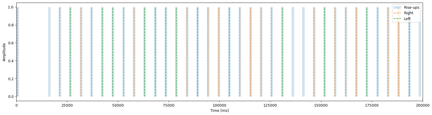
This simple latency correction consists of synchronize the hardware markers with the software markers, the LDR module is constantly sensing (the boardmode must be in analog) so the changes on the square signal (the rise-up) are compared with streamed markers and then the latency is corrected. The latency correction only affects the current HDF5Reader session, it does not store this correction on the file.